

In the previous three parts, we have created T0 VRF for an organization “OrganizationA”. We have also verified the VMware Cloud director configuration with vSphere and NSX-T Manager. We deployed two separate Tenants in different provider VDCs.
However, in the last blog, we created two tenants belonging to the same organization and created separate Tier-1 gateway per tenant. We have also created two separate logical segments for both tenants and connected to the corresponding Tier-1 gateways. We have also tested the network connectivity between Provider VDC belonging to the same organization. In this blog, we will configure an inter-VDC using data center groups and create a stretch Tier-1 gateway, and will perform failover (manually) of a VM in vAPP at Provider-VDC-1 to Provider-VDC-2, retaining the same IP addresses.
Routing between provider VDCs via stretch Tier-1 gateway
We will reuse previously created vAPP one in Tenant-A and another one in Tenant-B. A single segment-C will be created in vAPP of provider VDC-1 and attached to the existing Tier-1-Tenant-A gateway. The newly created segment “Segment-C” will be stretched using data center groups. Therefore, a new datacentre group “DC-1” will be created in Tenant-A and added to Tenant-B. “VM-1” Network connectivity will be tested from Provider VDC-1 and the same VM will be moved to tenant-B via manual failover., retaining the same IP address.
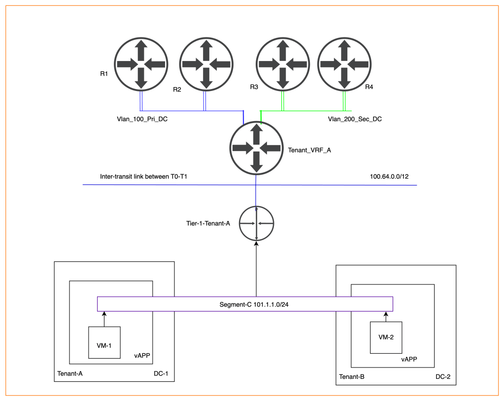
NB: In a production environment, VM will be moved to another provider VDC via a specific tool to minimize the downtime of an application running on the VM. We haven’t advertised Segment-C “101.1.1.0/24” subnet from Tier-0 to the physical environment. Therefore, make sure to follow the same process used in part-1 to advertise subnets to the physical routers.
Creating a Data center group in Provider VDC-1 (Tenant-A)
In this section, we will create one data center group, which will have starting VDC (Tenant-A) and participating VDC (Tenant-B).
| Starting VDC | Tenant-A |
| Name | Data-Center-Group1 |
| Participating VDC | Tenant-B |
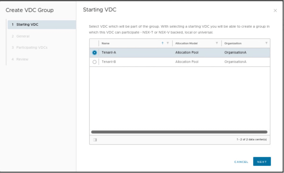
We need to provide the starting VDC as Tenant-A.
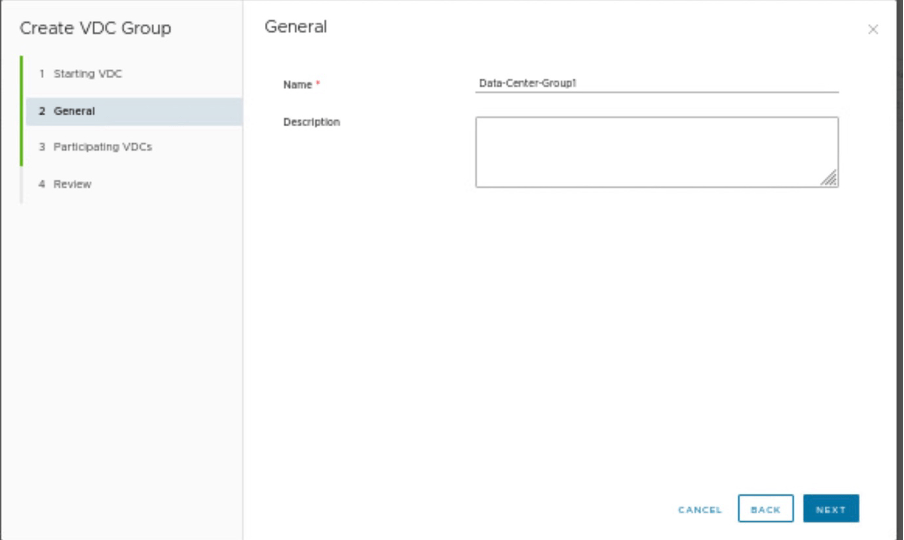
Provide the name of the data center group.
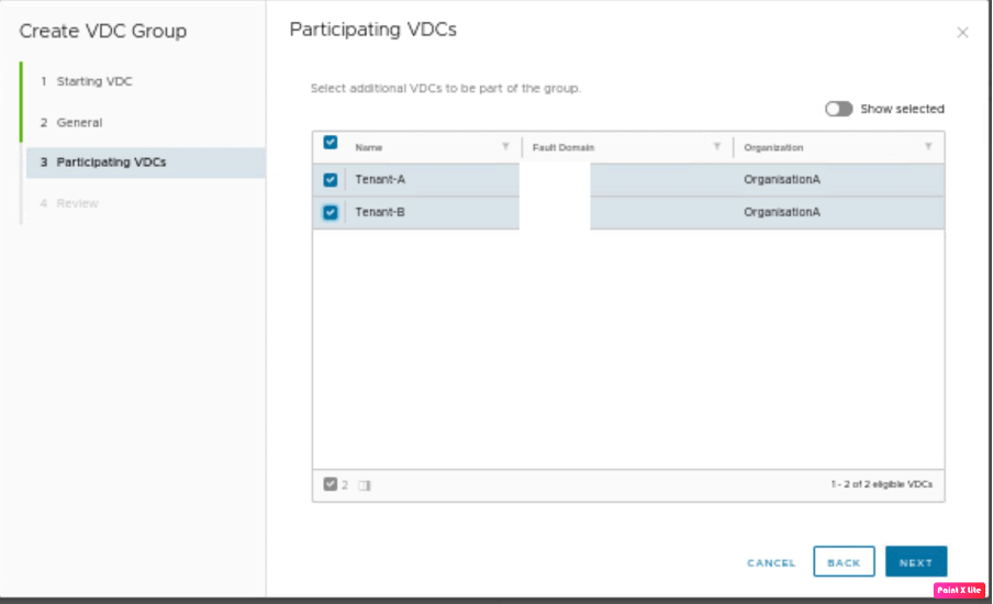
In this step, we need to provide the participating VDC, which is Tenant-B. This a lab scenario, therefore Fault domain for both Tenant-A and Tenant-B seems to be the same, however, in the production environment provide VDC-1 is one fault domain whereas VDC-2 is another fault domain.
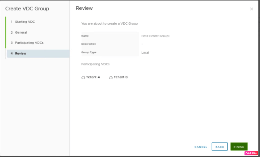
Review the configuration and create the data center group.

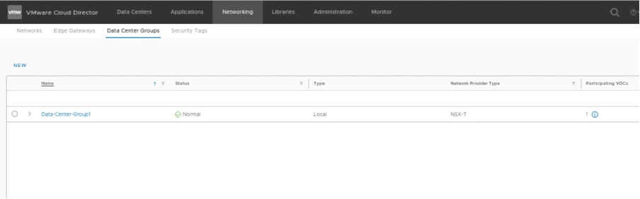
In the tenant portal of Tenant-A, verify that the Datacentre group “Data-Center-Group” has been created.
In the tenant portal of Tenant-B, verify that the Datacentre group “Data-Center-Group” has been created.
Creating a Stretch Tier-1 in Tenant-A and Tenant-B using Data Center Groups
In this step, we will stretch a new Tier-1-Tenant-AB, we will follow the similar approach, used earlier in NSX-T integration with VCD Part-3 “https://vxlearners.com/2023/07/16/nsx-t-integration-with-vcd-part-3/”
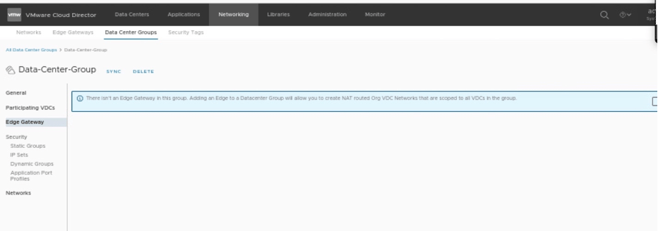
Go to the data center group, and create a new Tier-1 gateway, which will use as a stretch Tier-1 gateway. The new Tier-1 gateway will span across both Tenant-A and Tenant-B belonging to the same organization VDC.
| Data Center Group | Data-Center-Group1 |
| Tier-1 Gateway | Tier-1-Tenant-AB |
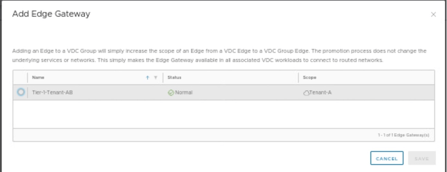
Select Tier-1 gateway, you want to stretch between Tenant-A and Tenant-B
Verifying the status of stretch Tier-1 gateway in Tenant-A
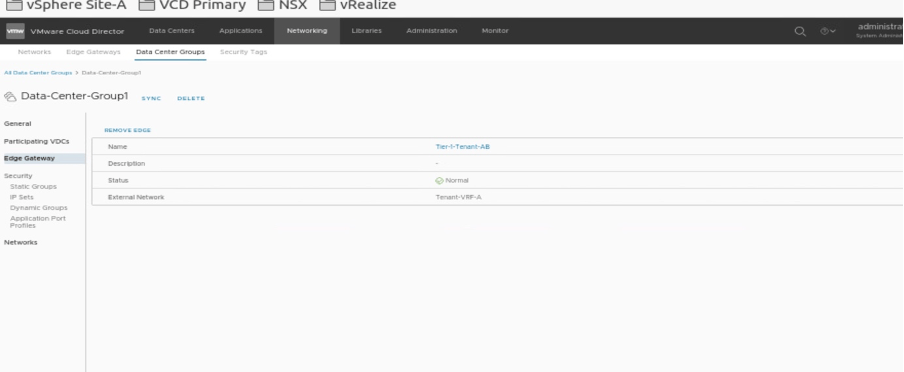
Go to Datacentre groups and verify that the new stretch cluster has been deployed.
Verifying the status of stretch Tier-1 gateway in Tenant-B
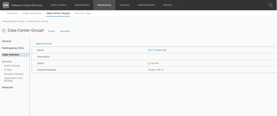
Go to Datacentre groups and verify that the new stretch cluster has been deployed.
Creating a stretch segment using Datacenter groups
We will create a separate segment Segment-C and connect it previously created stretch Tier-1 gateway.
| Data center group | Data-Center-Group1 |
| Network type | Routed |
| Segment Name | Segment-C |
| Gateway CIDR | 101.1.1.1/24 |
| IP pool | 101.1.1.10-101.1.1.20 |
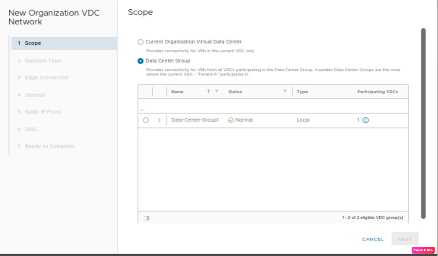
Go to the Tenant-A portal and create a new segment “Segment-C”.
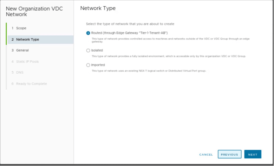
Select the type of Network, you are creating. As it is an NSX-T-backed segment, therefore, we have selected Network Type as “Routed”.
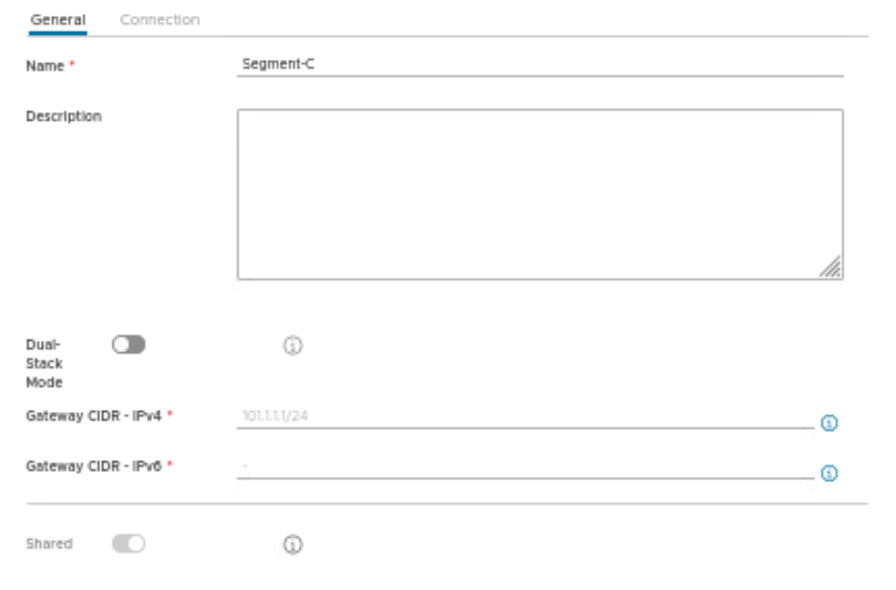
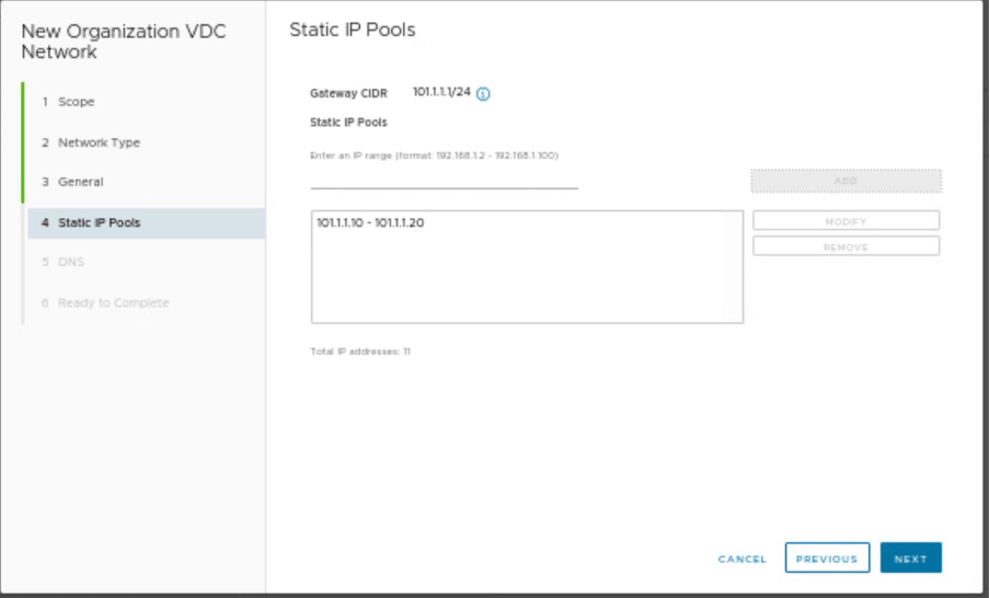
Provide the name of the segment along with gateway CIDR and IP pool details.
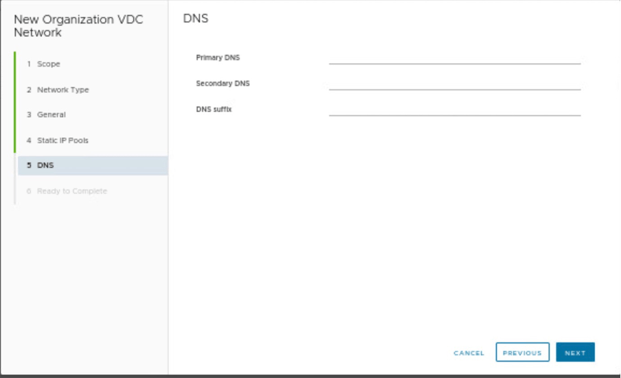
Providing DNS details, which are none in our scenario.
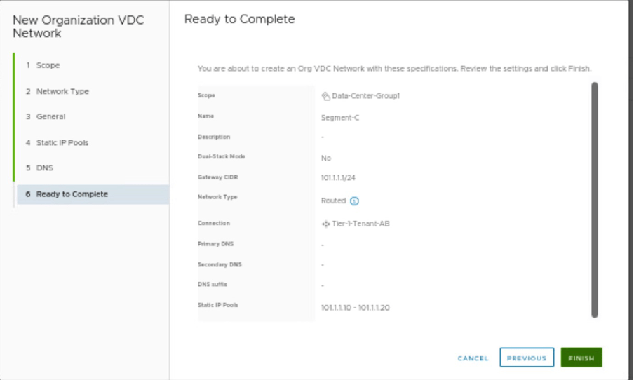
Review the configuration and create a Segment-C.
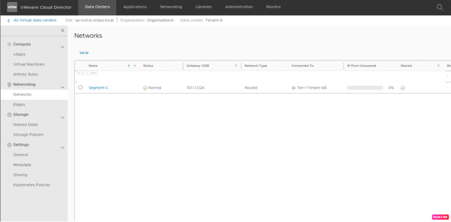
Verify on Tenant-A, that a newly created segment “Segment-C” is created.
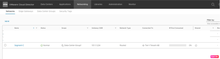
Verify on Tenant-B, that a newly created segment “Segment-C” is created.
Connect network interface of VMs in vAPP (Tenant-A-vAPP and Tenant-A-vAPP) to newly created Segment-C
In this session of the blog, we will change the network interfaces of both VM-1 and VM-2 in their respective vAPPs (Tenant-A-vAPP and Tenant-A-vAPP) to Segment-C, which was created in the previous section.
| VM name | VM-1 |
| vAPP name | Tenant-A-vAPP |
| Segment on NIC of VM-1 | Segment-C |
| IP address of VM-1 | 101.1.1.11/24 |
| VM name | VM-2 |
| vAPP name | Tenant-B-vAPP |
| Segment on NIC of VM-2 | Segment-C |
| IP address of VM-1 | 101.1.1.12/24 |
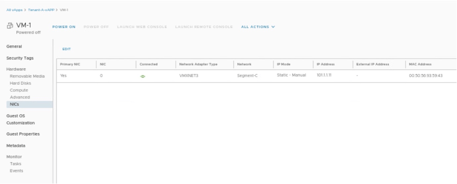
Changing NIC of VM-1 in Tenant-A-vAPP.
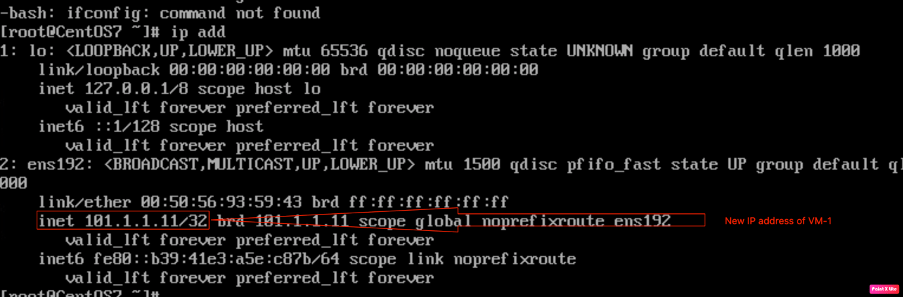
Checking the IP address of VM-1 via CLI.
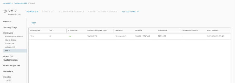
Changing NIC of VM-2 in Tenant-B-vAPP
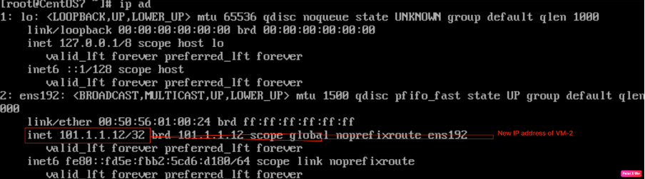
Checking the IP address of VM-2 via CLI.
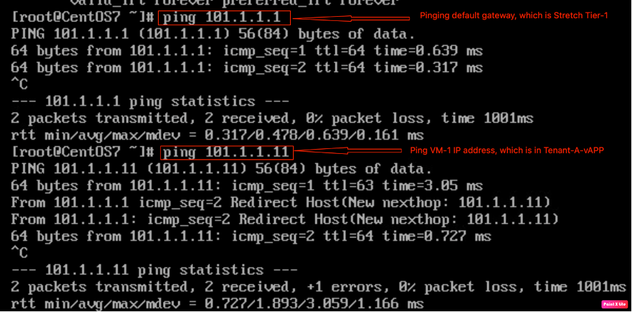
Checking IP connectivity from VM-2 to VM-1.
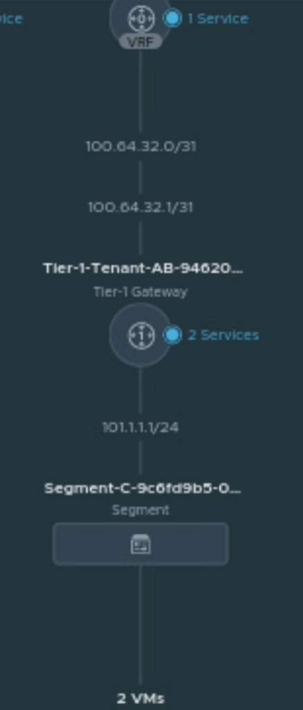
Verifying network connectivity in NSX-T
Check the network topology in NSX-T, go to Networking, and click on network topology to verify the network topology diagram.
Move the VM-1 from Tenant-A-vAPP to Tenant-A-vAPP and verify the network connectivity
In this step, we will perform the manual failover of VM-1 from Tenant-A-vAPP to Tenant-B-vAPP. However, in the production environment, specific tools will be used to move VMs (retaining the IP address) across Provider VDCs. Therefore, no downtime will be observed in a production environment.
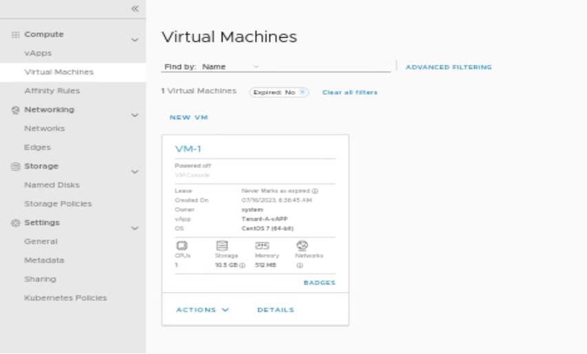
In this scenario, we have power-off the VM-1 and move it to Tenant-A-vAPP.
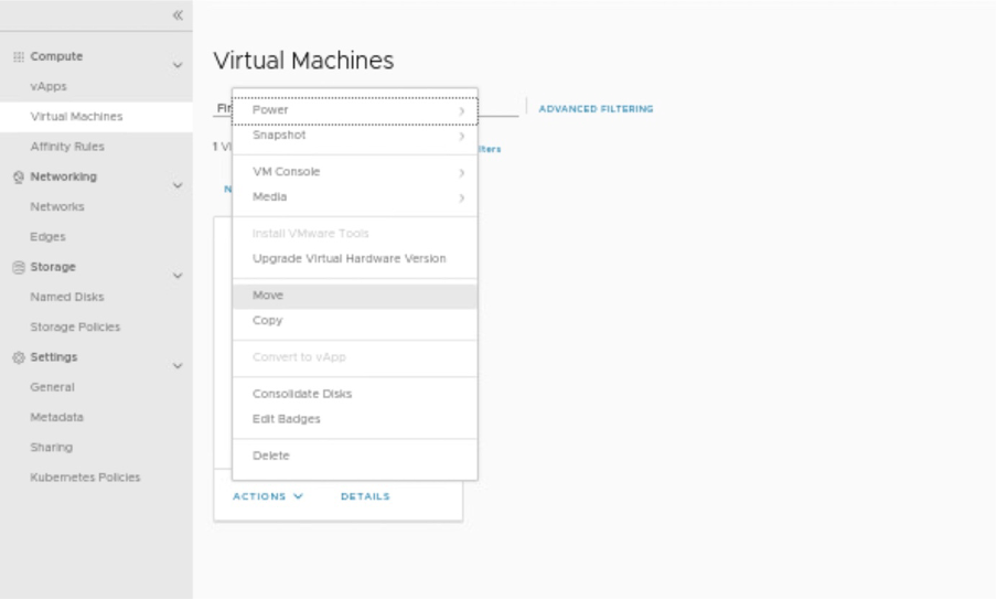
In this step, moving VM-1 to another vAPP which is in another DC.
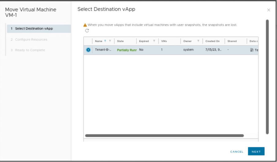
Select the vAPP, where the VM will be migrated.
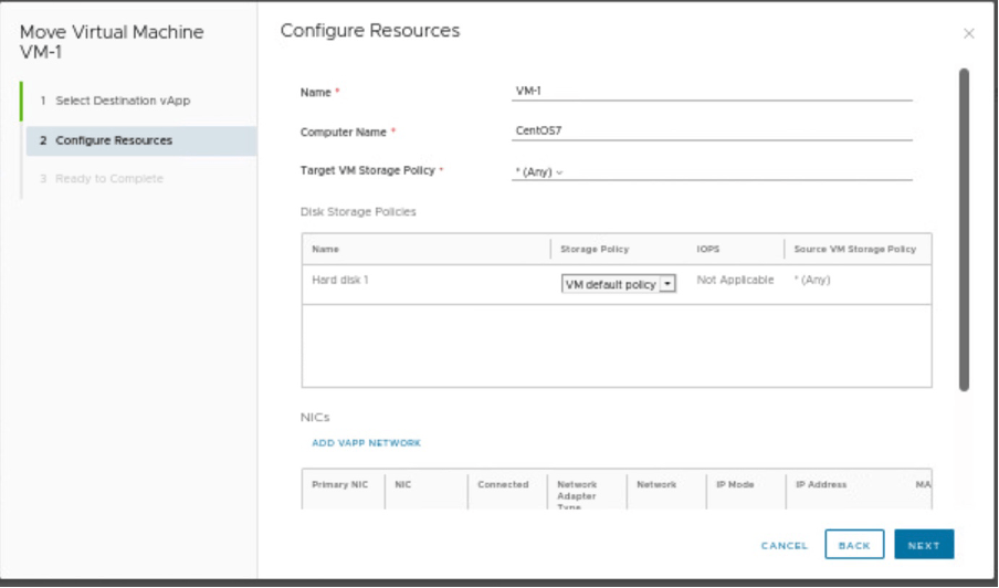
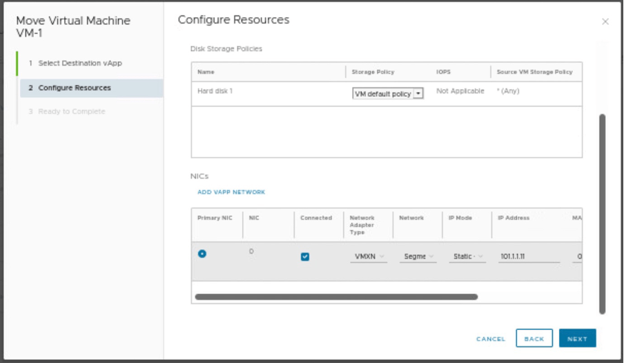
Verify the compute resources, storage policies and provide the Network details.
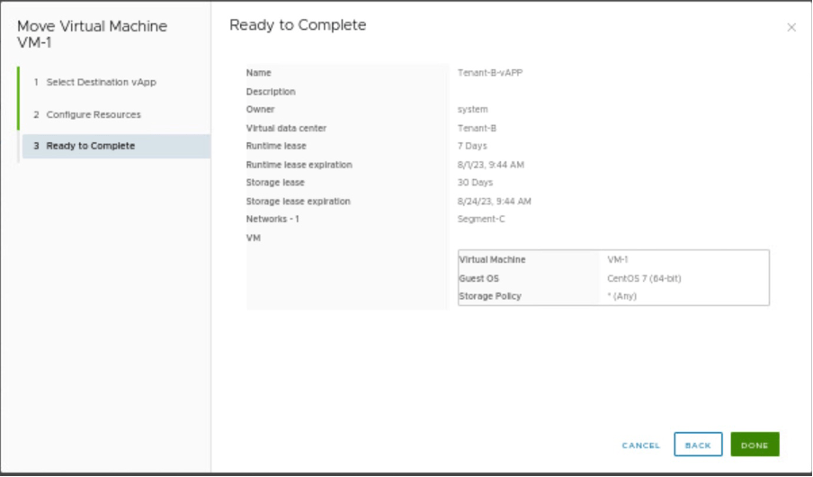
Review the configuration and move the VM to desired Provider VDC.
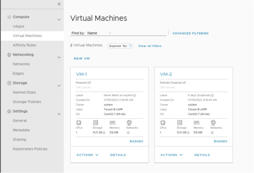
Verify in vAPP(Tenant-B-vAPP) of Provider VDC (Tenant-B) that both VMs are present.
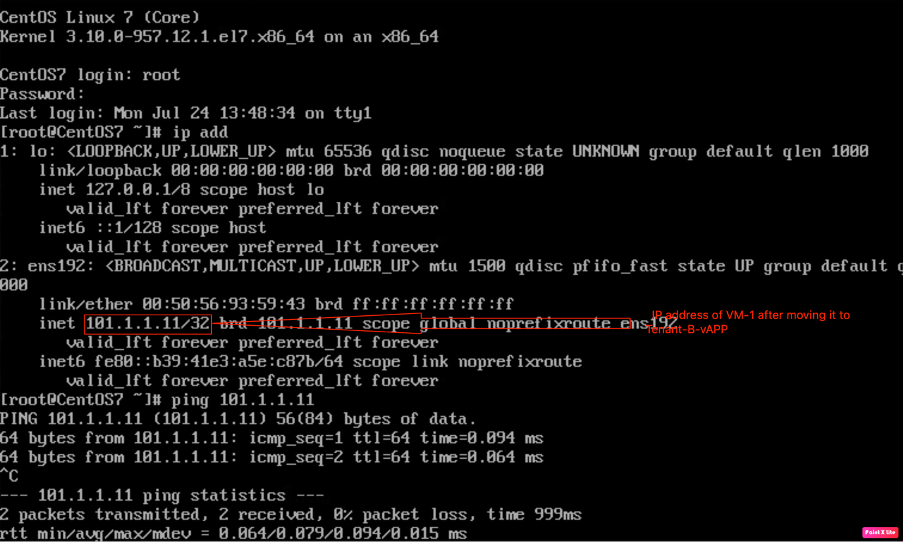
Powering on the VM-1 and verifying the IP connectivity between VM-1 and VM-2 belonging to the same Provider VDC.
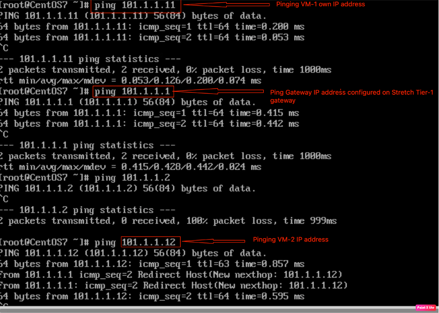
Pinging VM-2 and Gateway IP address from VM-1.
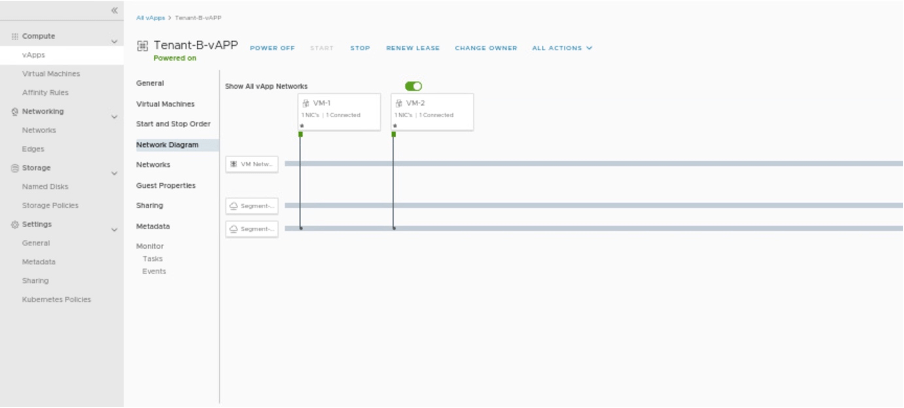
Checking Tenant-B-vAPP network diagram.
In Summary:
In the first blog, (https://vxlearners.com/2023/06/07/nsx-t-integration-with-vcd-part-1/), we discussed on NSX-T configuration required to onboard a tenant in VMware cloud director.
The second part, (https://vxlearners.com/2023/06/19/nsx-t-integration-with-vcd-part-2/), discussed the basic configuration required VMware cloud director required to configure OrgVDC and integrate it with NSX-T.
In the third part, (https://vxlearners.com/2023/07/16/nsx-t-integration-with-vcd-part-3/) created two tenants belonging to the same organization along with that separate Tier-1 gateways. Separate logical segments for both tenants have been connected to the corresponding Tier-1 gateways. Successfully tested the network connectivity between Provider VDC belonging to the same organization.
However, in this part, we have configured an inter-VDC using data center groups and created a stretch Tier-1 gateway, and we have also performed a failover of a VM-1 from Provider-VDC-1 to Provider-VDC-2, retaining the same IP addresses.
In the next series, we will configure Miro-segmentation in VCD using NSX-T. And in the future series, will integrate AVI, and (VMware K8s solution) Tanzu with VCD.


Leave a reply to vCD integration with NSX ALB part 3 – vxlearners Cancel reply