

In this blog, we will discuss how NSX-T is integrated with VMware cloud director for a single Tenant, which will be stretched across primary and secondary data centers to provide Network and Security capabilities. We will also test failure capabilities in case the primary provider VDC goes down.
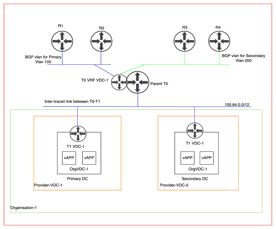
Topology Diagram
In this scenario, we will deploy a stretch Parent T0 (tier-zero) gateway, which will have 2 nodes at the primary site and two at the secondary DC. A separate VRF Tier-0 (tier-zero) be deployed for each OrgVDC. In this implementation, we are configuring only one VRF Tier (tier-zero) because the cloud provider has onboarded only customers. However, no traffic will be traversed from the secondary site because necessary manipulation will be achieved via AS prepended to make sure incoming and outgoing traffic will also traverse via the primary site. In case the primary site goes down, all traffic will traverse via the secondary site.
| Transport Zone | TZ_OVERLAY, TZ_VLAN |
| TEP IP Pool | TEP_POOL_FOR_EDGES_HOSTS |
NB: NSX-T managers are already deployed along with ESXi hosts, which are already prepared for NSX-T consumption. However, NSX-T edges are already deployed and created in an Edge cluster.
TEP pools and Transport Zone are already configured so we will leverage the existing pool for TEP and transports zones. ESXi hosts in both DR and primary environments are prepared with the same overlay transport zone. Primary and Secondary data centers have separate vDS (virtual data centers).
Make sure TEP subnets between the sites should be routed with a minimum MTU size of 1700 bytes.
vDS configuration
| Primary Data center | VDS-1 |
| Secondary Data Center | VDS-2 |
Current Hardware
| vCenter version | 7.0.2 |
| ESXi Host version | 7.0.2 |
| vDS version | 7.0.2 |
| NSX-T version | 3.1.1 |
| vCD (Cloud Director) | 10.3 |
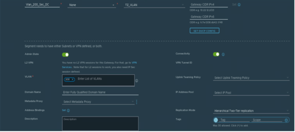
Creating Segments for BGP.
Below are the NSX-T vlan-based segments which will be used to configure BGP with physical routers.
| Segments | Vlan ID | Transport Zone |
| Vlan_100_Pri_DC | 100 | TZ_VLAN |
| Vlan_200_Sec_DC | 200 | TZ_VLAN |

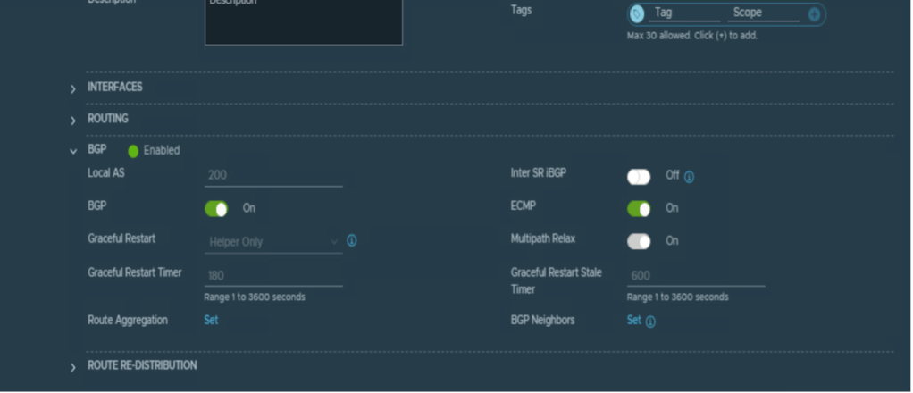
Creating Parent T0 Gateway
In this step, we will create a parent T0 (tier-zero) gateway, which is mandatory to configure the VRF T0 (tier-zero) gateway.
| Name | VCD_Tier_0 |
| Mode | Active-Active |
| Edge Cluster | edge_cluster_1 |
| Local AS | 200 |
| BGP | Enabled |
| Inter SR iBGP | Enabled |
| ECMP | Enabled |
NB: VRF T0 (tier-zero) will inherit all BGP characteristics from parent T0 (tier-zero) like local AS number, BGP timer details, inter SR iBGP, and so on. Therefore, it is mandatory to provide all this information in parent T0 (tier-zero).


Creating VRF Tier-0 Gateway
In this step, a VRF tier-0 (tier-zero) will be created, and it would be dedicated to Tenant-A.
| Name | Tenant_VRF_A |
| Parent T0 | VCD_Tier_0 |
| Edge Cluster | Inherited from Parent Tier-0 |

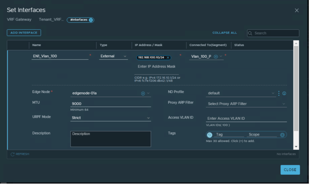
Creating interfaces on VRF Tier-0 for External connectivity
| VRF Tier-0 Gateway | Vlan | IP address EN1 | IP address EN2 | IP address EN3 | IP address EN4 |
| Tenant_VRF_A | 100 | 192.168.100.10 | 192.168.100.11 | NA | NA |
| Tenant_VRF_A | 200 | NA | NA | 192.168.200.10 | 192.168.200.11 |
Interfaces will be configured to provide connectivity to the physical environment. Below are the details of IP addressing and vlan configured on VRF Tier-0 (tier-zero).
NB: Two VLAN’s can be configured per DC for external connectivity, to achieve ECMP.
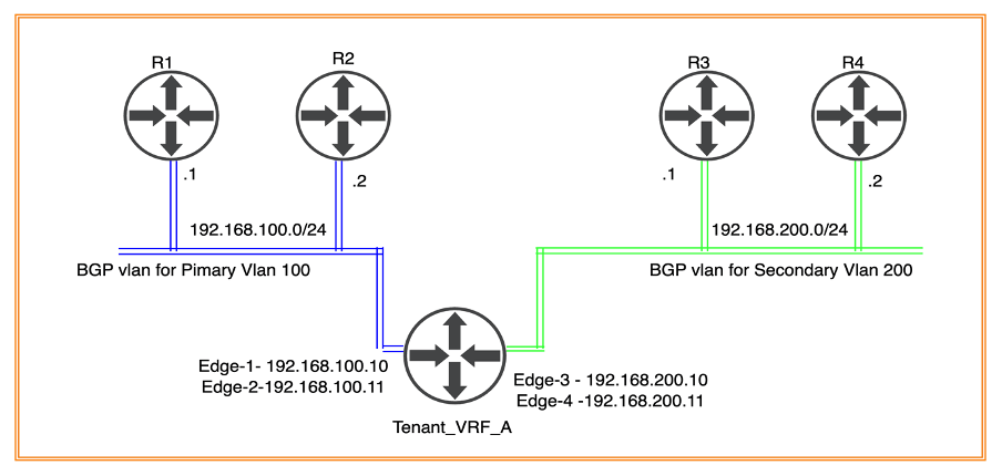
The above Diagram elaborates on Tier-0 (tier-zero) connectivity to physical routers R1, R1 (in Primary DC) and R3, R4 (in Secondary DC).
Interfaces configuration for Tier-0 connecting to physical router R1 and R2

Interfaces configuration for Tier-0 (tier-zero) connecting to physical router R3 and R4


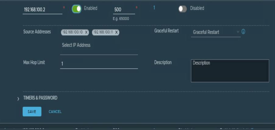
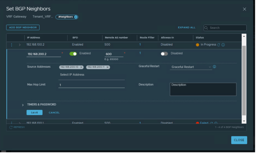
Configuring BGP for external connectivity
Tier-0 (tier-zero) VRF has inherited basic BGP configuration from the parent T0 router
BGP configuration for primary and secondary DC
| Tier-0 | Local AS | Remote AS | BGP neighbor IP | Tier-0 Edge IP |
| Tenant_VRF_A | 200 | 500 | 192.168.100.1 | 192.168.100.10 192.168.100.11 |
| Tenant_VRF_A | 200 | 500 | 192.168.100.2 | 192.168.100.10 192.168.100.11 |
| Tenant_VRF_A | 200 | 600 | 192.168.200.1 | 192.168.200.10 192.168.200.11 |
| Tenant_VRF_A | 200 | 600 | 192.168.100.2 | 192.168.200.10 192.168.200.11 |


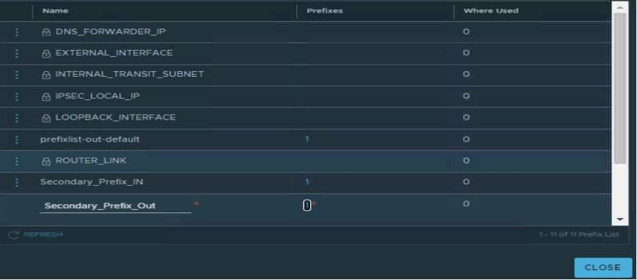
Adding prefix-list and route-map to make sure secondary Edges will only be preferred during any outage
In this section, we will add prefix list and route map to make sure Edge-1 and Edge-2 will be preferred over Edge-3 and Edge-4. Edge-3 and Edge-4 will be preferred only in case of outage at primary site.
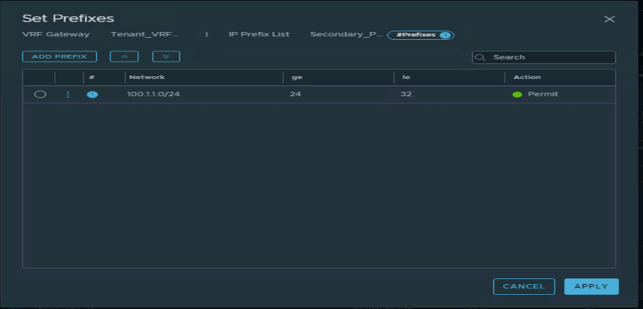
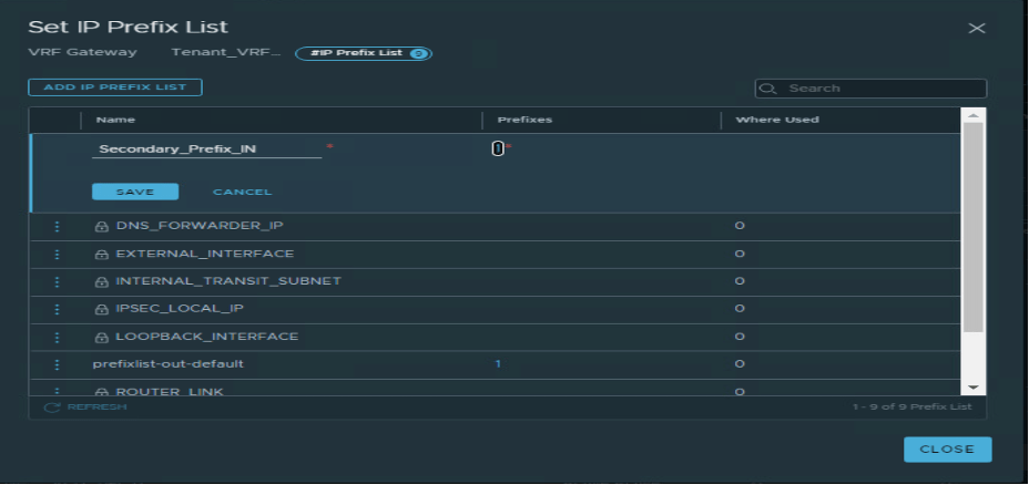
Adding prefix-list and route-map to make sure secondary Edges will only be preferred during any outage.
| Name | Subnet | Action |
| Secondary_Prefix_Out | 100.1.1.0/24 | Permit |
| Secondary_Prefix_In | Any | Permit |

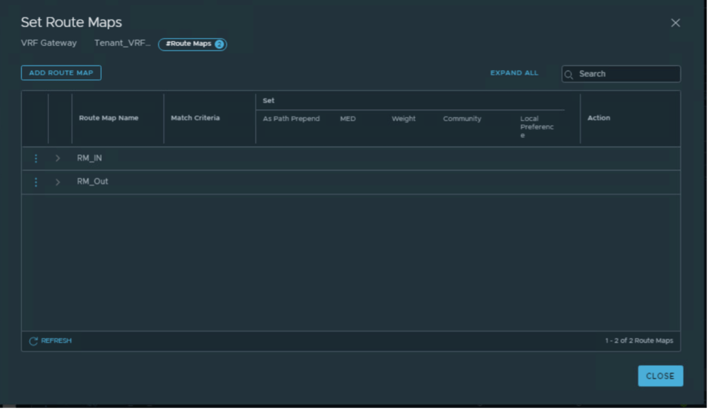
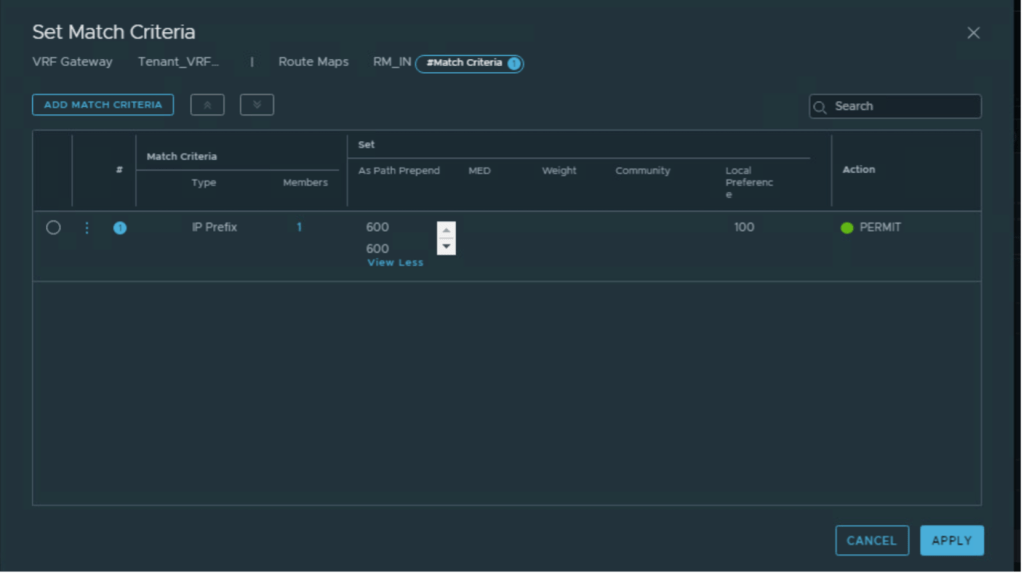
Two route-maps have been configured, as per below.
| Route Map Name | Prefix List | AS prepend |
| RM_IN | Secondary_Prefix_In | 600 600 |
| RM_OUT | Secondary_Prefix_Out | 600 600 |
Applying route-maps to R3 and R4 BGP neighbors.
| BGP neighbor IP address | IN | Out |
| 192.168.100.1, 192.168.100.2 | RM_IN | RM_Out |
| 192.168.200.1, 192.168.200.2 | RM_IN | RM_Out |


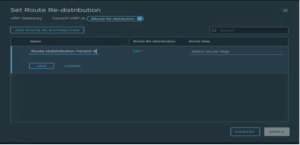
Advertising subnets from Tier-0 to the physical environment.
In this step, Tier-1 (tier-one) and Tier-0 (tier-zero) subnets will be advertised from Tier-0 (tier-zero). However, no route-redistribution is configured on Tier-1 (tier-one)as it doesn’t exist.
A new route-redistribution is created with the name “Route-Advertisement-Tenant-A” on VRF Tier-0 (tier-zero), which advertises only below networks.
- Tier-0 (tier-zero) – Connected interfaces and segments.
- Tier-1 (tier-one)– Connected interfaces and segments, NAT IP


Conclusion
In this article, we have discussed on NSX-T configuration required to onboard a tenant in VMware cloud director.
In the next couple of blogs, we will discuss the basic configuration of the VMware cloud director required to configure OrgVDC and integrate it with NSX-T. we will also configure a single tenant in two providers’ VDC, which will be backed up via different vCenter. We will also create two separate vAPPs, one for Provide-VDC-1 and another for Provide-VDC-2. Will perform basic network testing between VMs in different vAPPs. And at last, we will configure an inter-VDC using data center groups and create a stretch Tier-1 gateway, and verify the failover of vAPP from Provider-VDC-1 and Provider-VDC-2.


Leave a reply to Neha Jain Cancel reply